By Neil McGrath
I built the original discharger a couple of years ago and have used it quite sucessfully. The design did have a couple of problems, which were mainly to do with the bulbs. These did not like rough handling and had a tendency to break or blow during normal use. The bulbs also made the discharger quite bulky so it was not the most convenient tool to use.
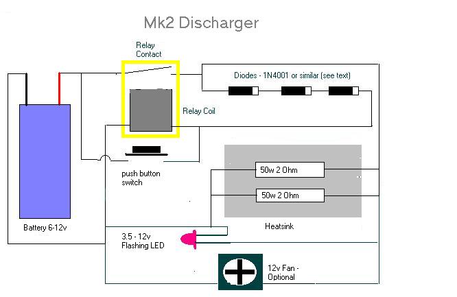
I decided to substitute the bulbs with wire wound resistors. The relay for the new discharger came out of my junk box and was originally intended for use as a car accessory relay designed for 12v operation. I checked to see if it would operate at 7.2v and it tested fine. The diodes also came out of the junk box and although they are not a common type they are broadly equivalent to the 1N4001 device used in the original design. The load resistors were two 2 ohm, 50watt, aluminium clad wire wound resistors, wired in parallel. These were bolted to the metal case after the mating surfaces were smeared with heat conductive grease. I purchased two 50 watt devices because the cost was less than buying a single 100w resistor. It is worth checking the cost of differently rated resistors with your local supplier as some component combinations of could work out cheaper than others.

You could mount the circuit on a heatsink or in metal box. I had a small heatsink in my junk box so attached this to the metal case to improve heat dissipation. Bear in mind that the resistors do get very hot. Think of the heat generated by a 50 Watt soldering iron. Your discharger will be radiating the same amount of heat, so do not leave it on any polished surfaces or on anything that could be damaged by high temperatures. I suggest that you use a bare metal box at least 6 inches square. Mounting the resistors well apart will help the heat to radiate more efficiently. Shortly after building this circuit, I replaced the CPU fan in my PC. The old fan was still working but it was starting to get noisy. I gave it a good squirt with WD40 and then installed it in the discharger case. This certainly helps the unit to keep reasonably cool, especially when discharging several batteries in quick succession.
One of the great advantages of using the bulbs on the old design was that you instantly knew when the cells were discharging and also when the discharging had stopped. With the new version I needed a visual indication to show that the unit was operating. For this I decided to use a flashing LED. The flashing circuit embedded within the LED allows it to work over quite a large voltage range, so this discharger can be used with battery voltages of between 3.5 and 12v. The LED is polarity conscious so check that you wire it the correct way around.
My model only needed two diodes to get the relay to switch off correct voltage, although the exact number required will depend on the characteristics of the relay used. Build the circuit as shown in the diagram (note the diode polarity) and use 4 diodes in series. Attach a fully charged battery and press the button. The relay should now switch on and the LED flash (if the relay does not switch, you will need a more sensitive relay possibly one with a lower voltage rating). When you release the button, the relay will either switch off or remain switched on (LED flashing). If it remains on, try adding another diode. If it switches off, remove a diode. You need to reach a stage where the unit just remains on and adding a diode causes it to switch off. This is the stage that you need to reach in order to set the cut off voltage.
I have seen many conflicting figures given for the optimum cut-off voltage for discharging a battery pack. The cell manufacturers usually quote around 0.9v per cell but I have settled on the nominal pack voltage minus 1.2v. I use this figure so that if one cell becomes totally discharged, it does not get a damaging reverse charge from the other cells in the pack during the discharge cycle.
Each diode will drop around 0.6v across its terminals, so start off by removing two diodes to reach the desired cut off point. (this will reduce the relay cut off voltage by 1.2 volts). Discharge a battery and note the cut off voltage using a multi-meter. Add or remove a diode to decrease or increase the cut-off voltage by approximately ½ a volt.
The standard design discharges at between 7 and 7.5 amps when used with a 7.2 v battery pack. You will need to adjust the value of the resistors to discharge at other rates. You will also need to improve the units cooling if you want to discharge at higher currents or voltage. I have added some formulas to the Fast Electric Calculator to help you select the correct value components.
Bear in mind that this circuit produces a lot of heat, so do not build it unless you are confident of your abilities. Regularly check for overheating and never leave it unattended during use. I have published this article to show the method of construction used on my own version of the unit. You must satisfy yourself that your own unit is safe and cannot cause injury or damage.